Summary of I/O Commands for the Arpanet IMP
19 Nov 2013
This document will describe the I/O addresses, commands and interrupts as currently employed in the IMP 3050 listing from 9/16/1973. This summary is based on an analysis of the listing and other documents related to the structure of the IMP.
Contents
- Background
- I/O instructions
- Device Addresses
- Device Descriptions
- Interrupt Unit
- Watch Dog Timer and Status Light Box
- Real Time Clock
- Task Interrupt/IMP Number
- Modem/Tip Configuration Flag
- Host Interface
- Modem Interface
- Interrupt Entry Point Addresses
- Dedicated Locations
- Interrupt Masks
- DMC Channel Numbers
Background
The IMP is based on the Honeywell DDP516 processor. In addition to the usual complement of peripherals the IMP has been augmented with some specifically designed cards. At present it is believed that the IMP that supports the 3050 IMP listing included at least:
- Honeywell DDP516 (or possibly 316) processor
- A TTY interface
- A light panel – a custom device that indicates the status of the attached lines
- Real Time Clock – A custom device that counts 100 usec clock ticks
- Certain custom “sense” options related to configuration
- Possibly a custom hardware interrupt to handle task dispatching
- DMC – a direct memory controller for transferring words from selected I/O devices to memory
#** I/O instructions**
The DDP516 I/O instructions have the following format:

- Opcode – defines the I/O instruction
- Function Code – selects a line to pulse (one of 16)
- Device Code – address of the device to control
The opcode may be one of:
| Opcode | Value | Description |
|---|---|---|
| INA | 54 | Input to A-register1 |
| OCP | 14 | Output Control Pulse as designated by Function Code |
| OTA | 74 | Output to device2 |
| SKS | 34 | Skip if ready line set |
| SMK | 74 | Special Mask – transfer A to interrupt control register |
Where the opcode in the table above is shown as two octal digits, but in a typical listing the opcode is broken across three octal digits.
Device Addresses
The following device addresses (octal) have been gleaned from the 3050 listing.
| Address | Device |
|---|---|
| 04 | TTY |
| 20 | Standard Interrupt Unit & Extension |
| 26 | Watchdog Timer and Status Light Box, Proc. Type |
| 40 | Real Time 100 usec Clock |
| 41 | Set task interrupt/IMP Number |
| 42 | IMP or TIP indicator |
| 50 | Host Interface 3 |
| 51 | Host Interface 4 |
| 60 | Host Interface 2 |
| 70 | Host Interface 1 |
| 71 | Modem Interface 1 |
| 72 | Modem Interface 2 |
| 73 | Modem Interface 3 |
| 74 | Modem Interface 4 |
| 75 | Modem Interface 5 |
Device Descriptions
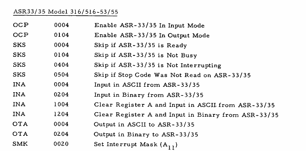
Teletype
The teletype is device address ‘04’. The following are the macros used to access the TTY in the listing. It appears that there are provisions for two TTY units, but only TTY A is used.
| Instruction | Opcode | FC | Dev | Description |
|---|---|---|---|---|
| 030004 | OCP | 00 | 04 | TTSIM – set TTY input mode |
| 030104 | OCP | 10 | 04 | TTSOM – set TTY output mode |
| 070004 | SKS | 00 | 04 | TTSRDY – skip on TTY ready |
| 070104 | SKS | 10 | 04 | TTSNBZ – skip on TTY not buzy |
| 070504 | SKS | 05 | 04 | TTSNSC - Skip if stop code not re |
| INA | 00 | 04 | TTINA – Input in ASCII | |
| INA | 02 | 04 | TTINB – Input in Binary | |
| 131004 | INA | 10 | 04 | TTINAC – get input character |
| 131204 | INA | 12 | 04 | TTINBC – Binary input (UNUSED) |
| 170004 | OTA | 00 | 04 | TTOTA – Output to TTY |
| 170204 | OTA | 02 | 04 | TTOTB - Binary output (UNUSED) |
The TTY chart from the DDP519 Programmers’ Reference Manual (page D-3):
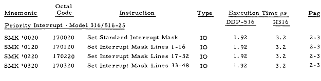
Interrupt Unit
Device address ‘20’ is used to set interrupt masks per the SMK instruction. The function code controls which bank of interrupts is to be set from the A register. In addition to the standard interrupt level the IMP apparently includes the next interrupt level the IMP includes an extension to allow interrupts on lines 1-16. This probably is where the “task” interrupt enters the system.
| Instruction | Opcode | FC | Dev | Description |
|---|---|---|---|---|
| 170020 | OTA | 00 | 20 | SMK – set “standard” interrupt mask |
| 170120 | OTA | 00 | 20 | SMK – set extension interrupt mask lines 1- |
Watch Dog Timer and Status Light Box
Presently the exact structure of this unit is unknown. It appears that the watch dog timer (WDT) generates an interrupt if it is not given an OCP pulse at periodic intervals (interval unknown). The light box appears to be 16 lights controlled by a register and is used to display modem and host status (see listing \@3355). There is an SKS function at this address, which appears to be a bit that indicates the type of processor. This function is defined, but is not used in the code.
| Instruction | Opcode | FC | Dev | Description |
|---|---|---|---|---|
| 030026 | OCP | 00 | 26 | Reset watch dog timer |
| 170026 | OTA | 00 | 26 | Set status lights |
| 070026 | SKS | 00 | 26 | AMI512 – machine type |
| - 0 = Other (316??) | ||||
| - 1 = 516 |
Real Time Clock
This appears to be a custom hardware that counts 100 usec pulses. From analysis of the code it appears that the RTC interrupt, CLOKIL, occurs on the carry of the eighth bit. This would correspond to 25.600 msec. It appears that the clock can only be read and that it is initialized to zero on power up. Not sure whether the clock counts up or down.
| Instruction | Opcode | FC | Dev | Description |
|---|---|---|---|---|
| 030040 | OCP | 00 | 40 | CLKON – turn clock on |
| 031040 | OCP | 10 | 40 | CLKOFF – stop real time clock |
| 131040 | INA | 10 | 40 | RDCLOK – read current time |
Task Interrupt/IMP Number
This appears to be a control pulse that can be used to set an external interrupt to indicate that a task has been posted to the task queue. The IMP number appears to be a hardwired number of the particular IMP.
| Instruction | Opcode | FC | Dev | Description |
|---|---|---|---|---|
| 030041 | OCP | 00 | 41 | TASK – set task interrupt |
| 131041 | INA | 10 | 41 | RDIMPN – probably hardwired IMP number |
The RDIMPN instruction is a form of the INA instruction. If the IMP number is not available the code executes the next instruction. If the IMP number is available the next instruction is skipped. Presumably the IMP number is always available.
Modem/Tip Configuration Flag
Allows the code to determine if the machine is an IMP or a TIP (Multi-Line Controller).
| Instruction | Opcode | FC | Dev | Description |
|---|---|---|---|---|
| 070042 | SKS | 00 | 42 | AMIMLC3 – |
| - 0 = IMP | ||||
| - 1 = MLC (Multi Line Controller) |
Host Interface
As shown above the host device addresses are not sequential probably because there are other important Honeywell devices already assigned to this area. In the following x is the device number that may vary from 1 to 4. The actual device address is shown above. MIDAS macros on page 4 of the listing show the construction of host instructions.
It appears that these controls go to the host interface. Data for the host is transferred through DMC channels.
| Instruction | Opcode | FC | Description | Listing |
|---|---|---|---|---|
| 303060 | OCP | 00 | HxROUT – Host “regular” output – start output to hos | t 17056 |
| 030170 | OCP | 01 | HxIN – start host input | 13200 |
| 030270 | OCP | 02 | HxFOUT – Host final output – final output to host | 16124 |
| 030370 | OCP | 03 | HxXP – Cross patch host (see listing p. 179) | --- |
| 030470 | OCP | 04 | HxUNXP – un-Cross patch host (see listing p. 179) | 01170 |
| 030570 | OCP | 05 | HxENAB – Enable host ?? | 16316 |
| 070070 | SKS | 00 | HxERR – skip on host error | 13172 |
| 070071 | SKS | 01 | HxRDY – skip on host ready | 21664 |
| 070072 | SKS | 02 | HxEOM – skip on host end-of-message (UNUSED ??) | 13303 |
| 070075 | SKS | 04 | HxFULL – skip on host buffer full ?? (UNUSED ??) | --- |
Modem Interface
The following controls go to the modem (M1, M2, M3, M4, M5). The actual data is transferred through the DMC. Modem addresses are given in the table above. Instruction codes are examples for particular modems. Page 4 of the listing gives the macros used to generate the instructions.
| Instruction | Opcode | FC | Description | Listing |
|---|---|---|---|---|
| 030071 | OCP | 00 | MxOUT – start modem output | 01062 |
| 030171 | OCP | 01 | MxUNXP – un-Cross Patch Modem (see listing p. 179) | 01266 |
| 030172 | OCP | 02 | MxLXP – set Line Cross Patch (see listing p. 179) | 21631 |
| 030173 | OCP | 03 | MxIXP – set Interface Cross Patch (see listing p. 179) | 21632 |
| 030471 | OCP | 04 | MxIN – start modem input (see listing p. 179) | 01223 |
| 070471 | SKS | 04 | MxERR – Skip on modem error | 10052 |
Interrupt Entry Point Addresses
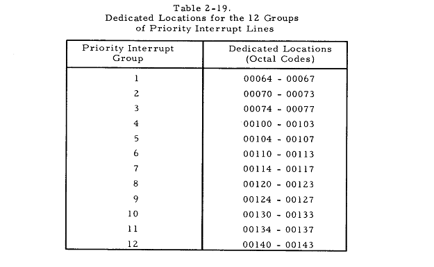
It appears that the interrupts vectors for the IMP peripherals have replaced those associated with the generic DDP 516. The basic interrupt structure of the DDP 516 is that there are 12 groups of four interrupt address, starting at 000064 and extending upward in block of four (probably this is related to packaging of the circuitry). There is a group “0” of four interrupts from 000060 to 000063, which are fixed. Here is a table from the Programmer’s Reference Manual related to the interrupt groups:
The IMP uses interrupt groups 1 through 4. As shown below.( these addresses have not all been verified.)
| Address | MACRO | Device | Description | Group | Line |
|---|---|---|---|---|---|
| 000060 | PFIL | Power Fail | |||
| 000061 | SWDTIL | Watch Dog ?? | |||
| 000062 | WDTIL | Watch Dog ?? | |||
| 000063 | STDIL | Standard Interrupt | |||
| 000064 | M1INTL | Modem 1 IN | Modem 1 input ready | 1 | 1 |
| 000065 | M2INTL | Modem 2 IN | Modem 2 input ready | 1 | 2 |
| 000066 | M3INTL | Modem 3 IN | Modem 3 input ready | 1 | 3 |
| 00067 | M4INTL | Modem 4 IN | Modem 4 input ready | 1 | 4 |
| H4OTIL | Host 4 Out (=M4INTL) | Host 4 output complete | 1 | 4 | |
| 000070 | M5INTL | Modem 5 IN | Modem 5 input ready | 2 | 5 |
| H3OTIL | Host 3 Out (=M5INIL) | Host 3 output complete | 2 | 5 | |
| 000071 | M1OTIL | Modem 1 OUT | Modem 1 output complete | 2 | 6 |
| 000072 | M2OTIL | Modem 2 OUT | Modem 2 output complete | 2 | 7 |
| 000073 | M3OTIL | Modem 3 OUT | Modem 3 output complete | 2 | 8 |
| 000074 | M4OTIL | Modem 4 OUT | Modem 4 output complete | 3 | 9 |
| H4INIL | Host 4 IN (=M4OTIL) | Host 4 input ready | 3 | 9 | |
| 000075 | M5OTIL | Modem 5 OUT | Modem 5 output complete | 3 | 10 |
| H3INIL | Host 34 IN (=M5OTIL) | Host 3 input ready | 3 | 10 | |
| 000076 | H1OTIL | Host 1 Out | Host 1 output complete | 3 | 11 |
| 000077 | H2OTIL | Host 2 Out | Host 2 output complete | 3 | 12 |
| 000100 | H1INIL | Host 1 IN | Host 1 input ready | 4 | 13 |
| 000101 | H2INIL | Host 2 IN | Host 2 input ready | 4 | 14 |
| 000102 | CLOKIL | Real time clock | 25.600 msec interrupt ?? | 4 | 15 |
| 000103 | TASKIL | Task ready | Set dynamically by the program when tasks are added to the task queue | 4 | 16 |
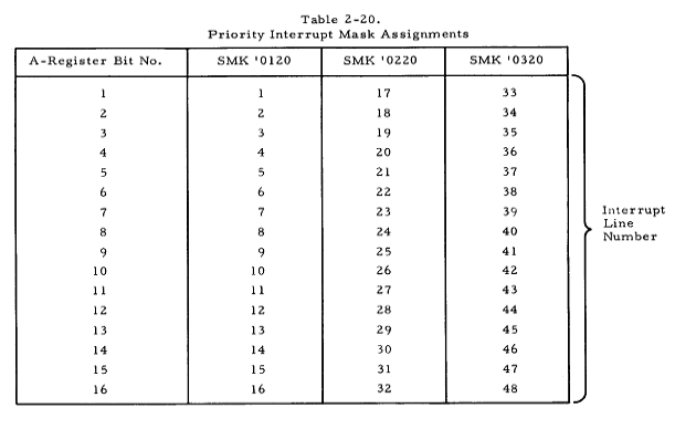
Masking of the interrupts is as shown in the table below (from the Programmer’s Reference Manual). The IMP makes use only of the interrupt lines 1-16, shown in gray below.
Note that some interrupt locations are assigned to two different devices (e.g., H4OTIL = M4INIL). These are shown in gray shading above. Certain configurations of host and modems are not allowed, so these interrupts will go to the particular device configured. For example, four hosts and four modems do not appear to be an allowed combination. This allows the interrupt to be shared. Listing page 43 is probably an enumeration of allowed host/modem configurations.
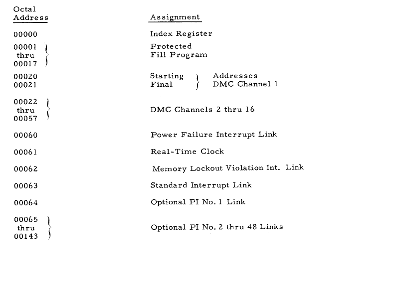
Dedicated Locations
The DDP516 has certain low memory locations that area dedicated as shown in the table below.
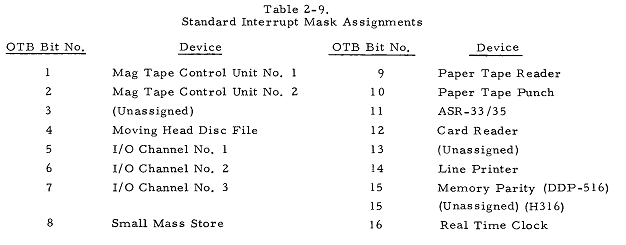
Interrupt Masks
Interrupts are organized into four banks. The first bank is standard and the following three banks are optional. The standard bank appears to be devoted to standard Honeywell peripherals. In the IMP the second bank is used to provide interrupts for the modems, host, program and timer. The table below shows the organization of the interrupt banks in reference to the set mask instructions that control each bank.
Mask bits in the standard interrupt bank are applied according to the following table:
The interrupts for the IMP specific devices are related to their device address as shown in the table of IMP special interrupts. Interrupts for a particular input are enabled if the bit is set to “0” they are disabled (“masked”) if the corresponding bit is set to 1.
| Address | Mask Bit | Function |
|---|---|---|
| 000064 | 1 | Modem 1 IN |
| 000065 | 2 | Modem 2 IN |
| 000066 | 3 | Modem 3 IN |
| 000067 | 4 | Modem 4 IN or Host 4 OUT |
| 000070 | 5 | Modem 5 IN or Host 3 OUT |
| 000071 | 6 | Modem 1 OUT |
| 000072 | 7 | Modem 2 OUT |
| 000073 | 8 | Modem 3 OUT |
| 000074 | 9 | Modem 4 OUT or Host 4 IN |
| 000075 | 10 | Modem 5 OUT or Host 3 IN |
| 000076 | 11 | Host 1 Out |
| 000077 | 12 | Host 2 Out |
| 000100 | 13 | Host 1 IN |
| 000101 | 14 | Host 2 IN |
| 000102 | 15 | Real time clock |
| 000103 | 16 | Task ready |
Note that certain interrupts and interrupt addresses are shared between modems and hosts. This means that only certain configurations are allowed. Specifically:
-
5 Modems and 2 Hosts
-
4 Modems and 3 Hosts
-
3 Modems and 4 Hosts
DMC Channel Numbers
The DDP516 supports 16 channels assignments according to the following table from the Programmer’s Reference. Normally, these would be allocated to various devices, like the tape, printer and disk. However, the IMP does not include any of these peripherals, so they channel assignments are freed up for use by the host and modems as shown following this table.
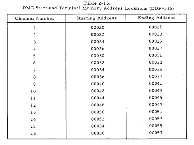
DMC pointers occur in pairs. For each DMC channel there are two consecutive words. The first word is the starting address for the channel and the second word is the ending address. For the modems and host attached to the IMP the address word pairs are stored as follows. For each device there is an input and output pointer designated as xx INBP and xxOTBP, respectively. The pointers for the modem and host DMC channels are defined on listing page 4 using MIDAS macros.
As with the interrupt address the DMC address for certain hosts and modems overlap. This is possible because the configurations are limited and conflicting host and modem configurations are not allowed. For example, there cannot be 4 hosts and 5 modems. Whether a channel represents an input or output channel is determined by the structure of the hardware and by the value of the high bit (bit 1) of the starting address. A value of “1” indicates the channel is setup for input. A value of “0” indicates the channel is setup for output.
| Name | Address | Function | Channel | Code Page |
|---|---|---|---|---|
| M1INBP | 000020 | Modem 1 input start address | 1 | 5 |
| 000021 | Modem 1 input end address | 1 | ||
| M2INBP | 000022 | Modem 2 input start address | 2 | 5 |
| 000023 | Modem 2 input end address | 2 | ||
| M3INBP | 000024 | Modem 3 input start address | 3 | 5 |
| 000025 | Modem 3 input end address | 3 | ||
| M4INBP | 000026 | Modem 4 input start address | 4 | 5 |
| 000027 | Modem 4 end start address | 4 | ||
| M5INBP | 000030 | Modem 5 input start address | 5 | 5 |
| H4OTBP | Host 4 output start address | 6 | ||
| 000031 | Modem 5 input end address | 5 | ||
| Host 4 output end address | ||||
| M1OTBP | 000032 | Modem 1 output start address | 6 | 5 |
| 000033 | Modem 1 output end address | 6 | ||
| M2OTBP | 000034 | Modem 2 output start address | 7 | 5 |
| 000035 | Modem 2 output end address | 7 | ||
| M3OTBP | 000036 | Modem 3 output start address | 8 | 5 |
| 000037 | Modem 3 output end address | 8 | ||
| M4OTBP | 000040 | Modem 4 output start address | 9 | 5 |
| 000041 | Modem 4 output end address | 9 | ||
| M5OTBP | 000042 | Modem 5 output start address | 10 | 5 |
| H4INBP | Host 4 input start address | 6 | ||
| 000043 | Modem 5 output end address | 10 | ||
| Host 4 input end address | ||||
| H1OTPB | 000044 | Host 1 output start address | 11 | 5 |
| 000045 | Host 1 output end address | 11 | ||
| H2OTPB | 000046 | Host 2 output start address | 12 | 5 |
| 000047 | Host 2 output end address | 12 | ||
| H2INPB | 000050 | Host 1 input start address | 13 | 5 |
| 000051 | Host 1 input end address | 13 | ||
| H2INPB | 000052 | Host 2 input start address | 14 | 5 |
| 000053 | Host 2 input end address | 14 | ||
| H3OTBP | 000054 | Host 3 output start address | 15 | 6 |
| 000055 | Host 3 output end address | 15 | ||
| H3INBP | 000056 | Host 3 input start address | 16 | 6 |
| 000057 | 16 |
-
Operation of this opcode is complex. The readiness of the device is tested before the device is read. If the device is not ready the next instruction is executed immediately. If the device is ready the data from the device is read into A and the next instruction is skipped. This allows the construction of simple ready wait loops. ↩
-
Operation with respect to device ready is similar to above. ↩
-
AMIMLC – probably means “Am I a Multi-Line Controller?” ↩
-
Only certain configurations of host and modem are allowed, so some interrupts overlap. ↩