IBM 7080 Simulator Usage
25-Jul-2018
Copyright © 2007, Richard Cornwell
Copyright © 1993-2007, Robert M Supnik
COPYRIGHT NOTICE and LICENSE are at the end of this document.
Contents
- Introduction
- Simulator Files
- IBM 7080 Features
- Stop conditions
- 3.1 CPU
- I/O Channels (CH0..CH6)
- Unit record devices.
- Magnetic Tape devices
- 7908 Devices
- 4 Symbolic Display and Input
- 5 Sim Load
- Character Codes
- COPYRIGHT NOTICE and LICENSE
[
Introduction
The IBM 7080 developed out of the IBM 702 which was a unique machine in that it had character addressed memory, however instructions had to be aligned on 5 character boundaries. Also it had to 256 character long accumulators which could be treated as variable length registers.
IBM replaced this machine with the IBM 705, where the second accumulator was replaced with 15 fixed offset registers, given 14 16 digit registers and 1 32 character register.
The 7080 enhanced this by adding in 3 more register sets that were used to talk to I/O devices.
Instructions addressed the last location of an instruction or field and proceeded to lower memory. All instructions were 5 characters long consisting of a 4 character address and 1 character instruction. Data length was either determined by the length of the referenced accumulator or by a signed character indicating start of next data field.
Simulator Files
| Subdirectory | File | Contains |
|---|---|---|
| I7000 | i7000_defs.h | IBM 7000 simulators general definitions |
| $0.00 | $0.00 | |
| i7000_chan.c | Generic channel interface. | |
| i7080_cpu.c | 7080 CPU, Channel, interface | |
| i7080_chan.c | 7080 Channel. | |
| i7080_sys.c | 7080 System interface | |
| i7000_cdr.c | 711 Card reader | |
| i7000_cdp.c | 721 Card punch | |
| i7000_com.c | 7750 Communications Controller | |
| i7000_con.c | Inquiry console. | |
| i7080_drum.c | Drum interface. | |
| i7000_dsk.c | 1301/2302 disk and 7238 drum controller. | |
| i7000_ht.c | 7340 Hypertape controller. | |
| i7000_lpr.c | 716 Line printer | |
| i7000_mt.c | 729 Tape controller. | |
| i7000_chron.c | Chrono Clock. |
IBM 7080 Features
The IBM 7080 simulator is configured as follows:
| Device Name(s) | Simulates |
|---|---|
| CPU | 7080 CPU with 160K of memory |
| CH0 | Unit record devices |
| CH1..4 | 754/7621 Tape controller channels |
| CH5..7 | 7908 Disk, Hypertape, controller channels |
| MTA | 729 Magnetic Tape Controller (Channel 20) |
| MTB | 729 Magnetic Tape Controller (Channel 21) |
| MTC | 729 Magnetic Tape Controller (Channel 22) |
| MTD | 729 Magnetic Tape Controller (Channel 23) |
| CHRON | Chrono Clock |
| HTA | 7340 Hypertape, default not included. |
| HTB | 7340 Hypertape, default not included. |
| INQ | Inquiry Station |
| CDR | 711 Card Reader |
| CDP | 721 Card Punch |
| LP | 716 Line Printer |
| DR | Drum memory. |
| DK | 1301/2302/7304 disk. |
| COM | 7750 communications controller. |
| COML | 7750 Communications lines. |
Channels B through D are mag tape channels 1,2,3,4.
Channels E & F are 7908 channels for disk, hypertape or 7750.
Stop conditions
The 7080 simulator implements several unique stop conditions:
- undefined CPU instruction
- undefined channel instruction
- XEC nesting exceeds limit
- divide check on a divide and halt instruction
- select of a non-existent channel
- 7607 select of a 7909 channel
- write select of a write protected device
- invalid file control format
- invalid message to 7750
- no buffer storage available for input character on 7750
- no buffer storage available for output character on 7750
The LOAD command will load a card binary image file into memory.
3.1 CPU
The CPU options include setting memory size and CPU type.
SET CPU 702                 Sets CPU to emulate 702.
SET CPU 705                 Sets CPU to emulate 705-I/II.
SET CPU 7053                Sets CPU to emulate 705-III.
SET CPU 7080                Sets CPU to emulate 7080.
SET CPU 10K                 Sets memory to 10K
SET CPU 20K                 Sets memory to 20K
SET CPU 40K                 Sets memory to 40K
SET CPU 80K                 Sets memory to 80K
SET CPU 120K                Sets memory to 120K
SET CPU 160K                Sets memory to 160K
SET CPU NO/EMU40K           Sets emulated memory limit to 40k
SET CPU EMU705              Sets CPU to emulate a 705-I/II.
SET CPU EMU7053             Sets CPU to emulate a 705-III.
SET CPU PROGRAM             Sets CPU to programmable stop mode.
SET CPU NONSTOP             Sets CPU to Non-stop mode
The 702 can support only 10k of memory. All 705’s modes can support up to 40K of memory.
The 7080 can support up to 160k of memory.
When in 7080 mode the machine starts as either a 705-I/II or a 705-III depending on mode of EMU705/EMU7053 switch. Also the EMU40K fixes the maximum memory for the 7080 to 40K until it enters 80 mode with EEM instruction.
CPU registers include the visible state of the processor as well as the control registers for the interrupt system.
Registers
| Name | Size(digits) | Comments |
|---|---|---|
| IC | 5 | Program Counter |
| A | 256 | Accumulator 1 |
| ASU1..15 | 256 | Accumulator 2 |
| SW | 6 | Switches |
| SW911..916 | 1 | Sense Switches 911 to 916 |
| STOP | 6 | Stop conditions |
| STOP0..5 | 1 | Individual Stop conditions |
If CPU set to PROGRAM and the stop flag is set to 1, and a 90x trigger is generated, the machine will stop. If flag is set to 0, no stop will occur. If CPU set to NONSTOP all errors must be checked by program.
The CPU can maintain a history of the most recently executed instructions.
This is controlled by the SET CPU HISTORY and SHOW CPU HISTORY commands:
SET CPU HISTORY             clear history buffer
SET CPU HISTORY=0           disable history
SET CPU HISTORY=n           enable history, length = n
SHOW CPU HISTORY            print CPU history
SHOW CPU HISTORY=n          print first n entries of CPU history
Instruction history trace shows the Instruction counter, the symbolic operator, and memory address and the contents of the selected register.
I/O Channels (CH0..CH6)
The 7080 supports up to 11 channels.
SET CHn UREC                Tapes are on unit record device.
SET CHn 7261                Tapes are on Data Synchronizer.
SET CHn 754                 Tapes are standard 705 drives.
SET Chn HS                  Set channel to High Speed.
Channel 0 is for unit record devices.
Channels 1 through 4 are for tape drives. These support the option of
Channels 5-10 are for 7908 devices. For CPU channels are defined as:
| Channel | CPU address |
|---|---|
| 0 | 0-1999 |
| 20 | 2000 or 0200 |
| 21 | 2100 or 0210 |
| 22 | 2200 or 0220 |
| 23 | 2300 or 0230 |
| 40 | 4000 7908 high speed channel. |
| 41 | 4100 7908 high speed channel. |
| 44 | 4400 7908 channel. |
| 45 | 4500 7908 channel. |
| 46 | 4600 7908 channel. |
| 47 | 4700 7908 channel. |
Registers
Channels have the following registers:
| Name | Size(digits) | Comments |
|---|---|---|
| ADDR | 5 | Channel Data Address |
| CMD | 1 | Channel Command. |
| FLAGS | 32 (binary) | Channel Flags |
For meaning of bits in FLAGS see i7000_defs.h.
The command:
SHOW CH Print summary of devices on channel
Unit record devices.
Inquiry Station (INQ)
The inquiry station allows for communications with the operating system.
The station is half duplex and will either print or accept input.
Whenever the computer sends a message it is prefixed with a ‘R’ character.
When the station is ready to receive input it prompts with a ‘I’. Input is buffered until the return character is entered.
Backspace will remove the last character typed.
An <esc> will send an interrupt to the processor to request it read a record from the console.
An <esc> while in input mode will cancel input mode and clear any typed message.
Card Reader (CDR)
The card reader (CDR) reads data from a disk file.
Cards are simulated as ASCII lines with terminating newlines.
Card reader files can either be text (one character per column) or column binary (two characters per column). The file type can be specified with a set command:
SET CDR FORMAT=TEXT         Sets ASCII text mode
SET CDR FORMAT=BINARY       Sets for binary card images.
SET CDR FORMAT=BCD          Sets for BCD records
SET CDR FORMAT=CBN          Sets for column binary BCD records.
SET CDR FORMAT=AUTO         Automatically determines format.
or in the ATTACH command:
ATTACH CDR <file>               Attaches a file
ATTACH CDR -f <format> <file>   Attaches a file with the given format.
ATTACH CDR -s <file>            Added file onto current cards to read.
ATTACH CDR -e <file>            After file is read in, the reader will
                                receive an end of file flag.
The card reader can be booted with the:
BOOT CDR
The CDR loads the first card into memory location 0 and transfers to location 4.
Error handling is as follows:
| error | processed as |
|---|---|
| not attached | report error and stop |
| end of file | out of cards |
| OS I/O error | report error and stop |
721 Card Punch (CDP)
The card reader (CDP) writes data to a disk file. Cards are simulated as ASCII lines with terminating newlines. Card punch files can either be text (one character per column) or column binary (two characters per column). The file type can be specified with a set command:
SET CDPn FORMAT=TEXT        Sets ASCII text mode
SET CDPn FORMAT=BINARY      Sets for binary card images.
SET CDPn FORMAT=BCD         Sets for BCD records.
SET CDPn FORMAT=CBN         Sets for column binary BCD records.
SET CDPn FORMAT=AUTO        Automatically determines format.
or in the ATTACH command:
ATTACH CDPn <file>                 Attaches a file
ATTACH CDPn -f <format> <file>     Attaches a file with the given format.
Error handling is as follows:
| error | processed as |
|---|---|
| not attached | report error and stop |
| OS I/O error | report error and stop |
716 Line Printer (LP)
The line printer (LP) writes data to a disk file as ASCII text with terminating newlines. Currently set to handle standard signals to control paper advance.
SET LPn NO/ECHO             Sets echoing to console of line-printer output.
SET LPn LINESPERPAGE=lpp    Sets number of lines per page on printer.
SET LPn SINGLE              Set printer to single spacing.
SET LPn DOUBLE              Set printer to double spacing.
SET LPn PROGRAM             Set printer to single spacing.
If the printer is set to PROGRAM spacing the first character of the print record controls spacing.
| Character (Octal) | Action |
|---|---|
| 060 | Suppress spacing. |
| 020 | Single space after. |
| 012 | Single space before. |
| 003 | Skip to channel 3 (every 5th line) |
| 002 | Skip to channel 2 (every 8th line) |
| 001 & 009 | Skip to channel 1 (or 9), (top of form). |
Error handling is as follows:
| error | processed as |
|---|---|
| not attached | report error and stop |
| OS I/O error | report error and stop |
Magnetic Tape devices
729 Magnetic Tape (MTA-D)
These come in groups of 10 units each.
Each individual tape drive support several options: MTA used as an example.
SET MTAn REWIND             Sets the mag tape to the load point
SET MTAn LOCKED             Sets the mag tape to be read only.
SET MTAn WRITEENABLE        Sets the mag tape to be writable.
SET MTAn LOW                Sets mag tape to low density.
SET MTAn HIGH               Sets mag tape to high density.
Options: Density LOW/HIGH does not change format of how tapes are written. And is only for informational purposes only.
Tape drives can be booted with:
BOOT MTxn Read in record into location 0.
ChronoClock
Disabled by default. This is a special 729 tape drive which returns the current time. It supports the option of setting the channel and drive that it will occupy.
Note: You must disable the real 729 drive that is is replacing.
The clock responds to Read and Backspace commands. A read results in a 10 character buffer being generated that has the Month, Day, Hour, Minutes, Seconds and Milliseconds.
This time is taken from the local computer time.
SET CHRON CHAN=n            Set channel for chrono clock.
SET CHRON UNIT=n            Sets the unit for the chrono clock.
Example: To set Chronoclock to unit A9 do the following:
SET MTA9 DISABLE
SET CHRON UNIT=9 CHAN=20
7908 Devices
These devices must be attached to a 7908 channel to work.
1301/1302/2302/7320 Disk devices
The 7631 file control supports up to ten devices, which can be 7320 drums, 1301 disks, 1302 disks, or 2302 disks. Unit types are specified with the SET command.
SET DKn TYPE=7320           Unit n is a drum
SET DKn TYPE=7320-2         Unit n is a drum (two modules)
SET DKn TYPE=1301           Unit n is a 1301 disk
SET DKn TYPE=130l-2         Unit n is a 1301-2 disk (two modules).
SET DKn TYPE=1302           Unit n is a 1302 disk
SET DKn TYPE=1302-2         Unit n is a 1302-2 disk (two modules).
SET DKn TYPE=2302           Unit n is a 2302 disk
Units can be SET ENABLED or DISABLED. In addition, units can be set to enable or disable formatting:
SET DKn FORMAT              Enable formatting
SET DKn NOFORMAT            Disable formatting
SET DKn HA2                 Enable writing of home address 2
SET DKn NOHA2               Disable writing of home address 2
SET DKn MODULE=n            Sets modules for unit, modules can only be even. 0 to 8.
SET DKn CHAN=n              Sets channel for unit (A-H)
SET DKn SELECT=n            Sets select on channel (0 or 1).
Formatting is disabled by default.
Error handling is as follows:
| error | processed as |
|---|---|
| not attached | report error and stop |
| OS I/O error | report error and stop |
Hypertape 7340 Tape drive (HTA)
These come in groups of 10 units each. The controller defines which channel the devices will be on. By default these devices are not installed.
SET HTA CHAN=n              Sets channel for unit (A-H).
SET HTA SELECT=n            Sets select on channel (0 or 1).
Each individual tape drive support several options: HTA used as an example.
SET HTAn LOCKED             Sets the mag tape to be read only.
SET HTAn WRITEENABLE        Sets the mag tape to be writable.
NOTE: Hypertape drives may not be working correctly since there is very little documentation available on them.
7750 Communications Controller (COM and COML)
The 7750 is modeled as a terminal multiplexer with 33 lines. It consists of two device: COM is the multiplexer controller, and COML is the individual lines.
For the first 32 lines, the 7750 performs input and output through Telnet sessions connected via a user-specified listening port.
The 33rd line is permanently attached to the simulator console window.
The ATTACH command specifies the port to be used for Telnet sessions:
ATTACH COM <port> set up listening port
where port is a decimal number between 1 and 65535 that is not being used other TCP/IP activities.
Each line (each unit of COML) can be set to one of twp modes: KSR-35 and KSR-37. In KSR-35 mode, lower case input and output characters are converted automatically to upper case, and parity is ignored. In KSR-37 mode, lower case characters are left alone, and even parity is generated on input. KSR-37 is the default.
Once COM is attached and the simulator is running, the 7750 listens for connections on the specified port. It assumes that any incoming connection is a Telnet connections. The connections remain open until disconnected either by the Telnet client, a SET COM DISCONNECT command,or a DETACH COM command.
SET COM DISCONNECT=n        Disconnect line n
SET COM CHAN=n              Set channel for com controller.
The 7750 implements the following special SHOW commands
SHOW COM CONNECTIONS        Displays current connections to the 7750
SHOW COM STATISTICS         Displays statistics for active connections
The 7750 implements the following special SET commands:
SET COMLn LOG=filename      Log output of line n to filename
SET COMLn NOLOG             Disable logging and close log file
SET COMLn KSR35             Set line n to ksr-35
SET COMLn KSR37             Set line n to ksr-37
SET COMLn 2741              Set line n to 2741
Registers
The controller (COM) implements these registers:
| Name | Size | Comments |
|---|---|---|
| ENABLE | 1 | Enable flag |
| STATE | 6 | Controller state |
| MSGNUM | 12 | Input message sequence number |
4 Symbolic Display and Input
The IBM 7080 simulator implements symbolic display and input. Display is controlled by command line switches:
-c                          Display/Enter as BCD character
-d/-s                       Display as character dump.
-m                          Display/Enter instruction mnemonics.
(none)                      Display/Enter as number.
Instruction input uses standard 7080 assembler syntax.
- <opcode> <address>,<ASU>
- <opcode> <address>
5 Sim Load
The load command looks at the extension of the file to determine how to load the file. Based on extension the file is converted to characters and loaded based on the 7080 load format.
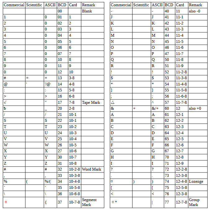
Character Codes
This is the mapping between character codes used by the simulator:
COPYRIGHT NOTICE and LICENSE
The following copyright notice applies to the SIMH source, binary, and documentation:
Original code published in 1993-2007, written by Robert M Supnik
Permission is hereby granted, free of charge, to any person obtaining a copy of this software and associated documentation files (the “Software”), to deal in the Software without restriction, including without limitation the rights to use, copy, modify, merge, publish, distribute, sublicense, and/or sell copies of the Software, and to permit persons to whom the Software is furnished to do so, subject to the following conditions:
The above copyright notice and this permission notice shall be included in all copies or substantial portions of the Software.
THE SOFTWARE IS PROVIDED “AS IS”, WITHOUT WARRANTY OF ANY KIND, EXPRESS OR IMPLIED, INCLUDING BUT NOT LIMITED TO THE WARRANTIES OF MERCHANTABILITY, FITNESS FOR A PARTICULAR PURPOSE AND NONINFRINGEMENT. IN NO EVENT SHALL ROBERT M SUPNIK BE LIABLE FOR ANY CLAIM, DAMAGES OR OTHER LIABILITY, WHETHER IN AN ACTION OF CONTRACT, TORT OR OTHERWISE, ARISING FROM, OUT OF OR IN CONNECTION WITH THE SOFTWARE OR THE USE OR OTHER DEALINGS IN THE SOFTWARE.
Except as contained in this notice, the names of the authors shall not be used in advertising or otherwise to promote the sale, use or other dealings in this Software without prior written authorization from each author.