IBM 7090 Simulator Usage
25-Jul-2018
Copyright © 2007, Richard Cornwell
Copyright © 1993-2007, Robert M Supnik
COPYRIGHT NOTICE and LICENSE are at the end of this document.
Contents
- Introduction
- Simulator Files
- IBM 7090 Features
- Stop conditions
- CPU
- Channel 7607 Devices and 704 devices.
- 7909 Devices
- 7289 High-Speed Drum (HD)
- Symbolic Display and Input
- Sim Load
- Character Codes
- COPYRIGHT NOTICE and LICENSE
Introduction
The follow up to the IBM704. Utilizing ideas learned from the Stretch IBM enhanced the 704 by adding multiple communications channels to speed up processing I/O devices. This allowed the machine to continue processing while the tapes or card readers transfered data.
Also this was one of the first machines to feature indirect addressing. Also added was an indicator register to hold flags and other information.
The IBM 709 was announced January 2, 1957 withdrawn April 7, 1960. Originally the IBM 709T later to be named the IBM 7090 by customers, the machine was a faster version of the IBM 709 implemented in transistors instead of tubes.
The IBM 7090 was announced December 30, 1958 withdrawn July 14, 1969.
The IBM 7090 also was built out of the same modules as the Stretch and used the same memory modules. The final enhancement was the IBM 7094, this added double percision arithmetic, faster processing, and 4 more index registers. The machine looked like a 7090 until extra indexing mode was entered, then instead of 3 registers begin or-ed together, the 3 bits selected one of 7 index registers.
It was latter upgraded to the 7094/II which was still faster.
The IBM 7094 & IBM 7094/II were announced January 15, 1962 withdrawn July 14, 1969.
IBM also developed two transistorized versions of the IBM 704, these were slower then the IBM 7090, and did not feature an indicator register or indirect addressing. But they came optionally with double precision floating point, and special character operating instructions.
It was also possible to purchase a 7040 without index registers or floating point. The machines were meant to be front ends to the IBM 7094, and a direct couple devices was sold, along with the ability to share 1301 drives between systems.
Unfortunately no software has been found for the IBM 7040/44.
The IBM 7094 was also one of the first machines to be modified to run time sharing. The Compatible Time Sharing System (CTSS) was developed by MIT to allow for the IBM 7094 to be shared by multiple people while still being compatible with FMS.
Simulator Files
To compile the IBM 7090, you must define USE_INT64 as part of the compilation command line.
| Subdirectory | File | Contains |
|---|---|---|
| I7000 | i7000_defs.h | IBM 7000 simulators general definitions |
| i7090_defs.h | IBM 7090 simulator specific definitions | |
| i7000_chan.c | Generic channel interface. | |
| i7090_cpu.c | 7090 CPU, Channel, interface | |
| i7090_chan.c | 7090 Channel. | |
| i7090_sys.c | 7090 System interface | |
| i7090_cdr.c | 711 Card reader | |
| i7090_cdp.c | 721 Card punch | |
| i7090_lpr.c | 716 Line printer | |
| i7090_drum.c | 733 Drum memory interface. | |
| i7000_com.c | 7750 Communications Controller* | |
| i7000_dsk.c | 1301/2302 disk and 7238 drum controller.* | |
| i7000_ht.c | 7340 Hypertape controller.* | |
| i7090_hdrum.c | CTSS High Speed Drum* | |
| i7000_mt.c | 729 Tape controller. | |
| i7000_chron.c | Chrono Clock.* |
If so desired instead of defining I7090, I704 can be defined and the files marked with ‘*’ above can be removed. This produces a smaller executable that will only emulate a IBM 704 computer.
IBM 7090 Features
The IBM 7090 simulator is configured as follows:
| Device Name(s) | Simulates |
|---|---|
| CPU | 7090 CPU with 32Kw/64Kw of memory |
| CH0 | 704 Unit record devices |
| CH1..8 | 7607/7909/7289 Channels |
| MT | 729 Magnetic Tape Controller (On CH0) |
| MTA | 729 Magnetic Tape Controller |
| MTB | 729 Magnetic Tape Controller |
| MTC | 729 Magnetic Tape Controller |
| MTD | 729 Magnetic Tape Controller |
| MTE | 729 Magnetic Tape Controller |
| CHRON | Chrono Clock |
| HTA | 7340 Hypertape, default not included. |
| HTB | 7340 Hypertape, default not included. |
| CDR | 711 Card Reader |
| CDP | 721 Card Punch |
| LP | 716 Line Printer |
| DR | Drum memory. |
| HD | CTSS High Speed Drum. |
| DK | 1301/2302/7304 disk. |
| COM | 7750 communications controller. |
| COML | 7750 Communications lines. |
Channels A through H, the corresponding magnetic tape controllers, and the file control, drum control , and communications control are initially set DISABLED.
The file control, drum control, and communications control can be assigned to any channel in the range B through H.
Stop conditions
The 7090 simulator implements several unique stop conditions:
- Undefined CPU instruction
- Undefined channel instruction
- XEC nesting exceeds limit
- Divide check on a divide and halt instruction
- Select of a non-existent channel
- 7607 select of a 7909 channel
- Write select of a write protected device
- Invalid file control format
- Invalid message to 7750
- No buffer storage available for input character on 7750
- No buffer storage available for output character on 7750
The LOAD command will load a card binary image file into memory.
CPU
The CPU options include setting memory size and cpu type. Also the special features required for used by the CTSS project:
SET CPU STANDARD            Standard CPU
SET CPU CTSS                Adds extra core memory for CTSS
SET CPU 704                 Sets CPU to emulate a 704
SET CPU 709                 Sets CPU to emulate 709 instructions
SET CPU 7090                Sets CPU to emulate 7090.
SET CPU 7094                Sets CPU to emulate 7094.
SET CPU 4K                  Sets memory to 4K
SET CPU 8K                  Sets memory to 8K
SET CPU 16K                 Sets memory to 16K
SET CPU 32K                 Sets memory to 32K
SET CPU TRUEIO              CPU executes I/O in CPU time.
SET CPU FASTIO              CPU detects I/O waits and shortens them
SET CPU NOEFP               Disables extended precision floating point.
SET CPU EFP                 Enables extended precision floating point.
SET CPU NOFPSM              Disables floating point significance mode.
SET CPU FPSM                Enables floating point significance mode.
SET CPU TIMER               Enables interval timer and interrupt.
SET CPU NOTIMER             Disables interval timer.
Memory size is 32KW on a standard CPU, 64KW on a CTSS CPU. Set notes below on setting up for CTSS.
The 7090 supported many options which were called RPQ’s, these include extended precision floating point instructions. These were similar to the later 7094 double precision floating point instructions. Significance mode allowed for better detection of bits during floating point operations.
FASTIO mode detects when the CPU is in a loop waiting for a channel to become available and then sets the simulation interval to run any pending I/O. This results in faster simulations without the CPU being aware of this. If the Timer is used, this might result in incorrect timing intervals.
CPU registers include the visible state of the processor as well as the control registers for the interrupt system.
| Name | Size | Comments |
|---|---|---|
| IC | 15 | Program Counter |
| AC | 38 | Accumulator |
| MQ | 36 | Multiplier Quotient |
| ID | 36 | Indicators register |
| KEYS | 36 | Front panel keys |
| XR1..XR7 | 15 | Index registers |
| SW1..SW6 | 1 | Sense Switches 1..6 |
| SW | 6 | Sense Switches |
| SL1..4 | 4 | Sense Lights 1..4 |
| ACOVF | 1 | Accumulator Overflow Indicator |
| MQOVF | 1 | MQ Overflow Indicator. |
| DVC | 1 | Divide Check indicator |
| IOC | 1 | I/O Check indicator |
| TM | 1 | Transfer Trap mode |
| CTM | 1 | Copy Trap mode |
| STM | 1 | Select Trap mode |
| FTM | 1 | Floating Trap mode |
| NMODE | 1 | Storage nullification mode |
| MTM | 1 | Multiple Tag mode |
| ENB | 36 | Interrupt enable register |
| INST_BASE | 1 | (CTSS) B core instruction execution |
| DATA_BASE | 1 | (CTSS) B core data access |
| BASE | 14 | (CTSS) relocation base block |
| LIMIT | 14 | (CTSS) address limit block |
The CPU can maintain a history of the most recently executed instructions.
This is controlled by the SET CPU HISTORY and SHOW CPU HISTORY commands:
SET CPU HISTORY             clear history buffer
SET CPU HISTORY=0           disable history
SET CPU HISTORY=n           enable history, length = n
SHOW CPU HISTORY            print CPU history
SHOW CPU HISTORY=n          print first n entries of CPU history
Instruction history trace shows the Instruction counter for the instruction, the AC and MQ before the execution, the computed Effective Address, the word read from storage, and the three index registers XR1, 2 and 4.
I/O Channels (CH0..CH8)
The 7090 supports up to 8 channels. Channel models include
7607                        standard multiplexer channel
7289                        high speed drum channel
7909                        advanced capabilities channel
Channel A is required and is always a 7607.
Channels are represented by a number: A=1, B=2, C=3, D=4, E=5, F=6, G=7, H=8.
Channel 0 is for 704 devices.
SET CHn 7607                Sets channel to be a 7607 type.
SET CHn 7909                Sets channel to be a 7909 type.
SET CHn 7289                Sets channel to be a 7289 type. (For CTSS Drum).
SET CHn FIXED               Fixes channel to specific type.
SET CHn AUTO                Default, channel configures based on devices on it.
Generally there is no need to worry about channel configurations, in auto mode they will configure to correct type to support devices attached to them. Or you will get an error when you attempt to run the simulation if there is a conflict.The default layout of devices will work for IBSYS and CTSS.
A show channel command will list out the devices currently assigned to this channel, or all channels if no specific channel is selected.
Channel 0 is a pseudo channel for 704 devices. Currently unit CR3, CP3, LP3,
DR0, and MT are set to this device.
Registers
Channels have the following registers:
| Name | Type | Size | Comments |
|---|---|---|---|
| ADDR | All | 16 | Channel Data Address |
| CMD | All | 6 | Channel Command. |
| WC | All | 15 | Channel Word Count |
| ASM | All | 36 | Assembly Register |
| LOCATION | All | 16 | Channel Location Counter |
| STATUS | All | 16 | Channel Device Status |
| SENSE | 7909 | 16 | Channel Sense Data |
| COUNTER | 7909 | 6 | Channel Counter |
| SMS | 7909 | 7 | Channel SMS Register |
For meaning of bits in STATUS and SENSE see i7000_defs.h.
Channel 7607 Devices and 704 devices.
These devices can only be attached to 7607 channels or to the Programed I/O channel 0.
711 Card Reader (CDR)
The card reader (CDR) reads data from a disk file.
Cards are simulated as ASCII lines with terminating newlines.
Card reader files can either be text (one character per column) or column binary (two characters per column). The file type can be specified with a set command:
SET CDRn FORMAT=TEXT        Sets ASCII text mode
SET CDRn FORMAT=BINARY      Sets for binary card images.
SET CDRn FORMAT=BCD         Sets for BCD records.
SET CDRn FORMAT=CBN         Sets for column binary BCD records.
SET CDRn FORMAT=AUTO        Automatically determines format.
or in the ATTACH command:
ATTACH CDRn <file>                  Attaches a file
ATTACH CDRn -f <format> <file>      Attaches a file with the given format
ATTACH CDRn -s <file>               Added file onto current cards to read
ATTACH CDRn -e <file>               After file is read in, the reader will
                                    receive and end of file flag
The card reader can be attached to either a 704 PIO channel or a 7607 channel. The channel can be changed by the following command:
SET CDRn CHAN=c Set this device to channel c.
The default assignments are:
CDR0                        Channel A(1)
CDR1                        Channel C(3)
CDR2                        Disabled
CDR3                        704 PIO.
If the simulator is compiled for only 704 then there is only one Card Reader called CDR.
The card reader can be booted with the:
BOOT CDRn Loads first 3 words of card.
Error handling is as follows:
| error | processed as |
|---|---|
| not attached | report error and stop |
| end of file | out of cards |
| OS I/O error | report error and stop |
721 Card Punch (CDP)
The card reader (CDP) writes data to a disk file. Cards are simulated as ASCII lines with terminating newlines. Card punch files can either be text (one character per column) or column binary (two characters per column). The file type can be specified with a set command:
SET CDPn FORMAT=TEXT        Sets ASCII text mode
SET CDPn FORMAT=BINARY      Sets for binary card images.
SET CDPn FORMAT=BCD         Sets for BCD records.
SET CDPn FORMAT=CBN         Sets for column binary BCD records.
SET CDPn FORMAT=AUTO        Automatically determines format.
or in the ATTACH command:
ATTACH CDPn <file>                 Attaches a file
ATTACH CDPn -f <format> <file>     Attaches a file with the given format.
The card punch can be attached to either a 704 PIO channel or a 7607 channel. The channel can be changed by the following command:
SET CDPn CHAN=c Set this device to channel c.
The default assignments are:
CDP0                        Channel A(1)
CDP1                        Channel C(3)
CDP2                        Disabled
CDP3                        704 PIO.
If the simulator is compiled for only 704 then there is only one Card Punch called CDP.
Error handling is as follows:
| error | processed as |
|---|---|
| not attached | report error and stop |
| OS I/O error | report error and stop |
716 Line Printer (LP)
The line printer (LP) writes data to a disk file as ASCII text with terminating newlines. Currently set to handle standard signals to control paper advance.
SET LPn NO/ECHO             Sets echoing to console of line-printer output
SET LPn CHAN=n              sets channel for this device
SET LPn LINESPERPAGE=lpp    Sets number of lines per page on printer.
The default assignments are:
LP0                         Channel A(1)
LP1                         Channel C(3)
LP2                         Disabled
LP3                         704 PIO.
The Printer supports the following SPRA n selection pulses for controlling spacing (spacing occurs before the line is printed):
| SPRA | Action |
|---|---|
| SPRA 1 | To top of form. |
| SPRA 2 | Single space. |
| SPRA 3 | Double space. Before printing line. |
| SPRA 4 | Triple space. Before printing line. |
| SPRA 9 | Suppress linefeed after print. Prints characters 73-120 |
| SPT | Will skip if any printer line has been pulsed. |
Default with no SPRA is to single space before printing.
Error handling is as follows:
| error | processed as |
|---|---|
| not attached | report error and stop |
| OS I/O error | report error and stop |
729 Magnetic Tape (MTA-D)
These come in groups of 10 units each. The controller defines which channel the devices will be on. MTx0 is unit 10.
SET MTx CHAN=n Set mag tape to channel n.
Each individual tape drive support several options: MTA used as an example.
SET MTAn ONLINE             Sets the mag tape drive on-line.
SET MTAn OFFLINE            Sets the mag tape drive off-line and not ready.
SET MTAn REWIND             Sets the mag tape to the load point.
SET MTAn LOCKED             Sets the mag tape to be read only.
SET MTAn WRITEENABLE        Sets the mag tape to be writable.
SET MTAn LOW                Sets mag tape to low density.
SET MTAn HIGH               Sets mag tape to high density.
Options: Density LOW/HIGH does not change format of how tapes are written. And is only for informational purposes only.
Online/Offline is part of a optional RPQ for the 7090 which adds the DRS/TRS instructions.
| Instr. | Function |
|---|---|
| DRS drive | Will set drive to off-line after current command is finished. Drive is not unloaded and can be re-enabled by setting it on-line. |
| TRS drive | Tests to see if the drive is on-line. If the drive is there and on-line it will skip the next instruction otherwise it takes the next instruction. |
These instructions were put in since accessing a unloaded tape drive would hang the CPU.
Tape drives can be booted with:
BOOT MTxn Read in first three words of record.
ChronoClock
Disabled by default. This is a special 729 tape drive which returns the current time. It supports the option of setting the channel and drive that it will occupy.
Note: You must disable the real 729 drive that is is replacing.
The clock responds to Read and Backspace commands. A read results in a 10 character buffer being generated that has the Month, Day, Hour, Minutes, Seconds and Milliseconds.
This time is taken from the local computer time.
SET CHRON CHAN=n            Set channel for chrono clock.
SET CHRON UNIT=n            Sets the unit for the chrono clock.
Example: To set Chronoclock to unit A9 do the following:
SET MTA9 DISABLE
SET CHRON UNIT=9 CHAN=A
733 Drum (DR)
This is the drum for 704/709 and possible 7090. Up to 16 units can be attached to the CPU, all are on pseudo channel 0. Each drum is 2048K words in size. They are all stored in one file.
SET DR0 UNITS=n Set number of units to of storage to attach.
Drum unit 0 can be booted with:
BOOT DR0 Read in first three words of record.
Drum unit can be assigned to a 7607 channel, but this is unsupported by the operating systems. Drum channel is changed with:
SET DR0 CHAN=n Set Drum to channel n.
7909 Devices
These devices must be attached to a 7909 channel to work.
1301/1302/2302/7320 Disk devices
The 7631 file control supports up to ten devices, which can be 7320 drums, 1301 disks, 1302 disks, or 2302 disks. Unit types are specified with the SET command.
SET DKn TYPE=7320           Unit n is a drum
SET DKn TYPE=7320-2         Unit n is a drum (two modules).
SET DKn TYPE=1301           Unit n is a 1301 disk
SET DKn TYPE=130l-2         Unit n is a 1301-2 disk (two modules).
SET DKn TYPE=1302           Unit n is a 1302 disk
SET DKn TYPE=1302-2         Unit n is a 1302-2 disk (two modules).
SET DKn TYPE=2302           Unit n is a 2302 disk
Units can be SET ENABLED or DISABLED. In addition, units can be set to enable or disable formatting:
SET DKn FORMAT              Enable formatting
SET DKn NOFORMAT            Disable formatting
SET DKn HA2                 Enable writing of home address 2
SET DKn NOHA2               Disable writing of home address 2
SET DKn MODULE=n            Sets modules for unit, modules can only be even. 0 to 8.
SET DKn CHAN=n              Sets channel for unit (A-H)
SET DKn SELECT=n            Sets select on channel (0 or 1).
SET DKn CTSS                Sets disk to use CTSS bootstrap.
SET DKn IBSYS               Sets disk to use IBSYS bootstrap.
Formatting is disabled by default.
All Disk units support bootstrapping with boot command. Bootstrap code is build based on whether CPU is in CTSS mode or not.
BOOT DKn Insert custom Loader into lower memory and start.
Error handling is as follows:
| error | processed as |
|---|---|
| not attached | report error and stop |
| OS I/O error | report error and stop |
Hypertape 7340 Tape drive (HTA/B)
These come in groups of 10 units each. The controller defines which channel the devices will be on.
SET HTA CHAN=n              Sets channel for unit (A-H).
SET HTA SELECT=n            Sets select on channel (0 or 1).
Each individual tape drive support several options: HTA used as an example.
SET HTAn LOCKED      Sets the mag tape to be read only.
SET HTAn WRITEENABLE Sets the mag tape to be writable.
NOTE: Hypertape drives may not be working correctly since there is very little documentation available on them.
Hypertape drives support bootstrapping with boot command.
BOOT HTAn Insert custom Loader into lower memory and start.
7750 Communications Controller (COM and COML)
The 7750 is modeled as a terminal multiplexer with 33 lines. It consists of two device: COM is the multiplexer controller, and COML is the individual lines.
For the first 32 lines, the 7750 performs input and output through Telnet sessions connected via a user-specified listening port.
The 33rd line is permanently attached to the simulator console window.
The ATTACH command specifies the port to be used for Telnet sessions:
ATTACH COM <port> set up listening port
where port is a decimal number between 1 and 65535 that is not being used other TCP/IP activities.
Each line (each unit of COML) can be set to one of twp modes: KSR-35 and KSR-37. In KSR-35 mode, lower case input and output characters are converted automatically to upper case, and parity is ignored. In KSR-37 mode, lower case characters are left alone, and even parity is generated on input. KSR-37 is the default.
Once COM is attached and the simulator is running, the 7750 listens for connections on the specified port. It assumes that any incoming connection is a Telnet connections. The connections remain open until disconnected either by the Telnet client, a SET COM DISCONNECT command,or a DETACH COM command.
SET COM DISCONNECT=n        Disconnect line n
SET COM CHAN=n              Set channel for com controller.
The 7750 implements the following special SHOW commands
SHOW COM CONNECTIONS        Displays current connections to the 7750
SHOW COM STATISTICS         Displays statistics for active connections
The 7750 implements the following special SET commands:
SET COMLn LOG=filename      Log output of line n to filename
SET COMLn NOLOG             Disable logging and close log file
SET COMLn KSR35             Set line *n* to ksr-35
SET COMLn KSR37             Set line *n* to ksr-37
SET COMLn 2741              Set line *n* to 2741
Registers
The controller (COM) implements these registers:
| Name | Size | Comments |
|---|---|---|
| ENABLE | 1 | Enable flag |
| STATE | 6 | Controller state |
| MSGNUM | 12 | Input message sequence number |
7289 High-Speed Drum (HD)
The 7289 (also known as the 7320A) high-speed drum was a late addition to CTSS. Very little is known about the device, other than what is used in the CTSS sources.
The drum can be changed to different channels with the:
SET HD0 CHAN=n              Set Drum to channel n.The channel must be
                            configured as a 7289 type channel. Otherwise
                            the drum will not work.
SET HD0 UNITS=n             Sets the number of 256K drums on the unit.                                                                       |
Error handling is as follows:
| error | processed as |
|---|---|
| not attached | report error and stop |
Drum data files are buffered in memory; therefore, end of file and OS I/O errors cannot occur.
Symbolic Display and Input
The IBM 7090 simulator implements symbolic display and input. Display is controlled by command line switches:
-c                          Display/Enter as BCD character
-m                          Display/Enter instruction mnemonics
-l                          Display as lisp pointer.
(none)                      Display/Enter as octal number.
Instruction input uses standard 7090 assembler syntax. There are two basic instruction classes: memory reference and index reference.
Memory reference instructions have the format
memref{*} address{,tag}
Index reference instructions have the format
idxref{*} address,{tag},decrement
Specific instructions may disallow indirect addressing or limit the size of the tag, address, or decrement fields.
Channel (I/O) instructions have the same basic two formats.
Sim Load
The load command looks at the extension of the file to determine how to load the file.
| Ext. | Format/Action |
|---|---|
| .crd | Loads a card image file into memory. standard 709 format + 1 card loader. |
| .oct | Loads an octal deck: address <blank> octal <blank> octal… |
| .sym | Loads a 709 symbolic deck. address instruction.. address BCD string address OCT octal octal |
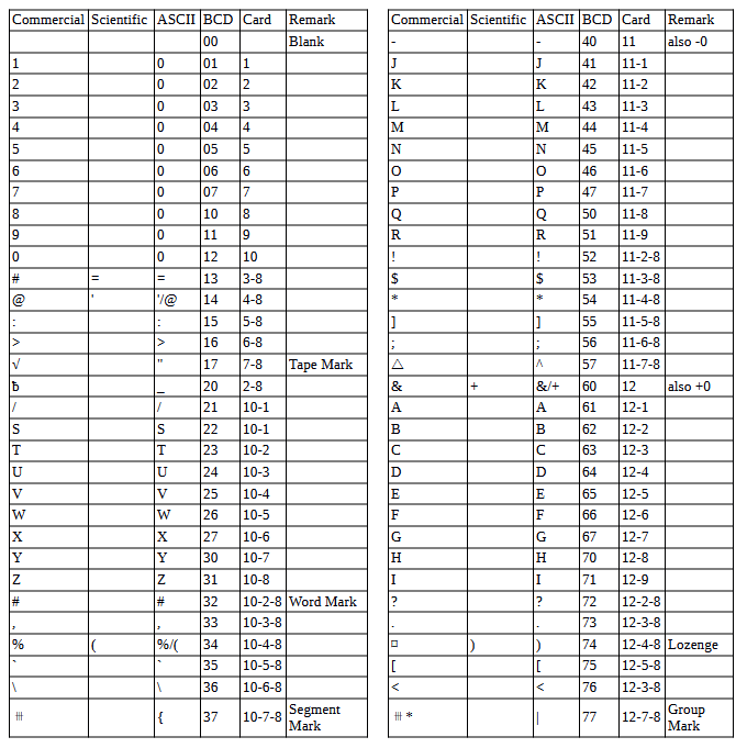
Character Codes
This is the mapping between character codes used by the simulator:
COPYRIGHT NOTICE and LICENSE
The following copyright notice applies to the SIMH source, binary, and documentation:
Original code published in 1993-2007, written by Robert M Supnik
Permission is hereby granted, free of charge, to any person obtaining a copy of this software and associated documentation files (the “Software”), to deal in the Software without restriction, including without limitation the rights to use, copy, modify, merge, publish, distribute, sublicense, and/or sell copies of the Software, and to permit persons to whom the Software is furnished to do so, subject to the following conditions:
The above copyright notice and this permission notice shall be included in all copies or substantial portions of the Software.
THE SOFTWARE IS PROVIDED “AS IS”, WITHOUT WARRANTY OF ANY KIND, EXPRESS OR IMPLIED, INCLUDING BUT NOT LIMITED TO THE WARRANTIES OF MERCHANTABILITY, FITNESS FOR A PARTICULAR PURPOSE AND NONINFRINGEMENT. IN NO EVENT SHALL ROBERT M SUPNIK BE LIABLE FOR ANY CLAIM, DAMAGES OR OTHER LIABILITY, WHETHER IN AN ACTION OF CONTRACT, TORT OR OTHERWISE, ARISING FROM, OUT OF OR IN CONNECTION WITH THE SOFTWARE OR THE USE OR OTHER DEALINGS IN THE SOFTWARE.
Except as contained in this notice, the names of the authors shall not be used in advertising or otherwise to promote the sale, use or other dealings in this Software without prior written authorization from each author.